AirBox V2 Design Document
AirBox is an open educational project in which participants build their own solar-powered air quality monitoring station from scratch. The project comes in two variants:
- EduKit Indoor option centred on CO2 measurement for classrooms, offices, and home.
- Full Outdoor station that adds particulate matter (PM2.5/PM10), volatile organic compounds (VOCs), and nitrogen oxides (NOx) for street-level and urban environmental monitoring.
Both variants include temperature and humidity sensing, which serve both as standalone comfort metrics and as compensation inputs for the gas and particle sensors.
Each station connects over Wi-Fi and publishes its readings to a shared MQTT broker, making the data available in near-real-time to anyone. On the frontend, a Grafana dashboard presents the data on an interactive geographical map — every deployed AirBox appears as a data point, allowing participants and the public to explore hyperlocal air quality patterns across an entire city or campus.
Because all harvested data is public by design, AirBox doubles as a citizen-science platform: the more stations that are built and deployed, the denser and more useful the shared dataset becomes.
On the hardware side, AirBox is designed to run indefinitely off a small 10V solar panel backed by a single-cell Li-ion battery, with USB available as a secondary or indoor-only power source.

Connection instructions
You can find instructions for connecting your AirBox V2 to WiFi here
MCU Options
The following table provides information on a few MCU setups that were evaluated for AirBox. For our application, we are using for a deep-sleep capable microprocessor that is able to wake on an internal RTC clock. Wireless connectivity is vital for reporting data to AirBox servers.
Since AirBox is an engineering-focused course initially aimed at atudents, ease of programming is a big plus.
| Spec | nRF5340 + nRF7002 | RP2040 + CYW43439 (Pico W) | ESP32-S2 (Winner) |
ESP32-S3 |
|---|---|---|---|---|
| CPU | 2× ARM Cortex-M33: app core @ 128 MHz + net core @ 64 MHz; no ULP | 2× ARM Cortex-M0+ @ 133 MHz; no ULP | 1× Xtensa LX7 @ 240 MHz + RISC-V ULP coprocessor | 2× Xtensa LX7 @ 240 MHz + RISC-V ULP coprocessor |
| Wi-Fi | 802.11ax (Wi-Fi 6), 2.4 + 5 GHz | 802.11 b/g/n (Wi-Fi 4), 2.4 GHz | 802.11 b/g/n, 2.4 GHz | 802.11 b/g/n, 2.4 GHz |
| Bluetooth | BLE 5.3 (via nRF5340 radio) | BLE 5.2 (via CYW43439) | No | BLE 5.0 |
| Other protocols | Thread, Zigbee, NFC, 802.15.4, ANT | — | — | — |
| USB | USB 2.0 full-speed | USB 1.1 (host & device) | USB OTG (full-speed) | USB OTG (full-speed) |
| SDK | Zephyr | Arduino IDE | Arduino IDE | Arduino IDE |
| Running current (CPU active) | 5 mA + ~70 mA (nRF7002 Wi-Fi TX) | 25–30 mA, up to 300 mA (Wi-Fi TX) | 20–31 mA, up to 240 mA (Wi-Fi TX) | 20–68 mA, up to 240 mA (Wi-Fi TX) |
| RTC Sleep | 1.7 µA (System ON + net core RTC + 64 KB RAM) | 1.3 mA (Pico W board-level) | 20 µA (deep-sleep, RTC timer) | 8 µA (deep-sleep, RTC timer) |
The nRF5340 + nRF7002 combo is a very professional option with many IoT-specific communication protocols, allowing advanced integration with sensor networks and automation tooling.
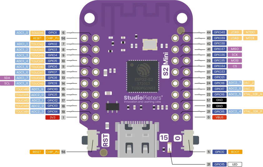
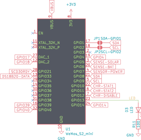
For the initial phase of AirBox V2, ESP32-S2 looks like the best option that checks all the required boxes. We will use ESP32-S2 for the development of AirBox, more specifically the Wemos S2 Mini board to allow students to easily solder it to the board.
Sensors
The parameters that matter most depend on whether the station lives indoors or outdoors:
- Indoor air quality is dominated by CO2 — it is the single best proxy for ventilation adequacy and directly correlates with occupant comfort, cognitive performance, and drowsiness. Levels above ~1 000 ppm signal insufficient fresh-air exchange. VOCs (volatile organic compounds from furniture, cleaning products, cooking, and building materials) are the second priority, as they contribute to "sick building" symptoms even when CO₂ looks acceptable. Particulate matter is less critical indoors unless the station is placed in a kitchen, workshop, or a building near a busy road.
- Outdoor air quality centres on particulate matter (PM2.5 and PM10) — fine particles from traffic, industry, construction, and wildfires are the pollutants with the strongest documented impact on respiratory and cardiovascular health. NOx (nitrogen oxides, primarily from combustion engines and power plants) is the second key metric and a regulated pollutant in most air-quality indices. VOCs are relevant near industrial sites or heavy traffic but are less universally important outdoors than PM and NOx. CO₂ is largely irrelevant in open air because ambient concentrations (~420 ppm) vary little and are not a health concern at those levels.
- Both Indoor and Outdoor confiogurations must be able to measure temperature and humidity.
| Spec | SCD30 | SEN54 | SEN55 | SEN66 |
|---|---|---|---|---|
| Product family | SCD (CO₂ module) | SEN5x (environmental node) | SEN5x (environmental node) | SEN6x (environmental node) |
| CO2 | ✅ NDIR dual-channel, 400–10 000 ppm ±(30 ppm + 3 % m.v.) | ❌ | ❌ | ✅ PASens (photoacoustic), 400–10 000 ppm ±(30 ppm + 3 % m.v.) |
| PM1 / PM2.5 / PM4 / PM10 | ❌ | ✅ (laser scattering) | ✅ (laser scattering) | ✅ (MEMS-based SPS6x) |
| PM2.5 accuracy | — | ±5 µg/m³ (0–100) / ±10 % (100–1000) | ±5 µg/m³ (0–100) / ±10 % (100–1000) | ±5 µg/m³ (0–100) / ±10 % (100–1000) |
| VOC Index | ❌ | ✅ (SGP40-based) | ✅ (SGP40-based) | ✅ |
| NOx Index | ❌ | ❌ | ✅ | ✅ |
| Temperature | ✅ | ✅ (SHT4x-based) | ✅ (SHT4x-based) | ✅ |
| Relative humidity | ✅ | ✅ (SHT4x-based) | ✅ (SHT4x-based) | ✅ |
| Interface | I2C / Modbus / PWM | I2C / UART | I2C / UART | I2C |
| Supply voltage | 3.3–5.5 V | 5 V | 5 V | 3.3 V or 5 V |
| Current (measuring) | 19 mA | 63 mA (fan + laser active) | 63 mA (fan + laser active) | 55 mA (all sensors active) |
| Current (idle) | 5.6mA | 2.6mA | 2.6mA | 3mA |
| Module size | 35 × 23 × 7 mm | 41 × 41 × 12 mm | 41 × 41 × 12 mm | 41 × 41 × 11 mm |
| Design lifetime | >15 years (CO₂ cell) | >10 years | >10 years | >10 years |
The SCD30 has no true idle mode — the IR detector draws current continuously. Increasing the sampling interval from 2s to 30s reduces average current to ~5.6 mA at the cost of slower response time (~135 s vs. ~20 s).
SCD30 provides the vital CO2 metric for indoor air quality while being affordable. SEN66 sensor provides all the important metrics, and is suitable for both indoor and outdoor sensing.
We will build connectors for both sensors on the pcb:
- AirBox V2 EduKit with SCD30 for strictly indoor use.
- AirBox V2 with SEN66 for AQI data, that will work indoor and outdoor.
| AirBox V2 EduKit | AirBox V2 |
|---|---|
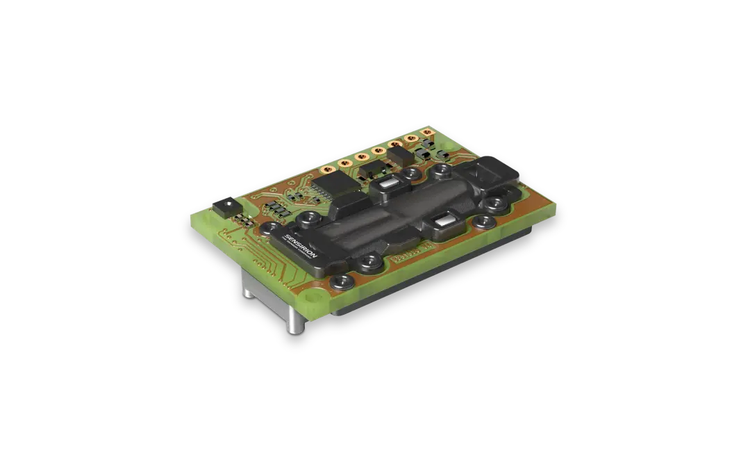
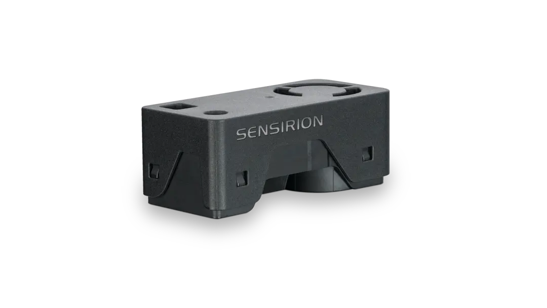
| SCD30 is normally pcb-mounted using pin headers, but for our project it is best to be able to mount the sensor flexibly inside the enclosure. We will attach JST-XH headers to the sensor and connect using a detachable cable. | SEN66 connects using its built-in connector (crimped wires will be done by hand) to the PCB. Case design should respect recommandations from Sensirion's Mechanical Design Guidelines. |
 |
 |
The sensors talk to the Airbox over I²C. There are plenty of nice resources on the internet to understand it, but we highly recommend checking out these slides made by Alexandru Radovici for the PM Course at UPB to understand the structure of the transactions.
https://embedded-rust-101.wyliodrin.com/docs/fils_en/lecture/06
Power Management
Between measurement cycles the MCU enters deep sleep and relies on its internal RTC to wake at the next scheduled interval.
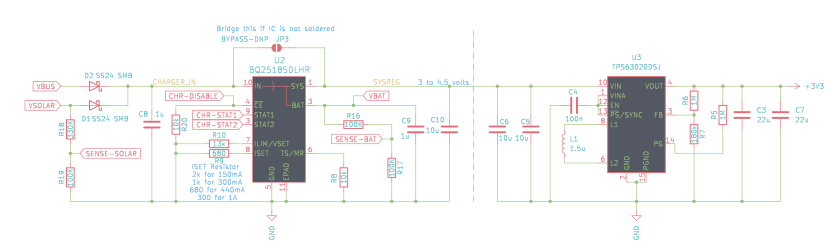
The station accepts power from two sources - a USB connector for bench or indoor use and a 10V solar panel for outdoor deployments - with each input protected by a Schottky diode so that neither source can back-feed into the other.
Behind the diodes sits a TI BQ25185, a single-cell Li-Ion charge controller with an integrated power-path that seamlessly routes current between the solar panel, the USB supply, and the battery depending on what is available at any given moment.
The BQ25185 comes in a 2.5 × 2.5 mm QFN package, which is too fine-pitch for hand soldering; it will therefore be pre-soldered to the AirBox PCB before participants receive their kits, so that the power stage is guaranteed to work.
The ESP32 must be able to measure the state of charge of the battery. This will be done by measuring the battery voltage trough a 2x 100kOhm resistive divider. There are a few factors affecting this reading:
- Sensors and ESP networking draw a large amount of current. They will make the battery under-report. Therefore, the charge measurement must be done before sensors and networking are engaged.
- If the battery is charging, the voltage will read artificially high. To compensate, the ESP must temporarely turn off charging by driving high the
/CEpin of BQ25185 and then execute the reading.
Voltage at the battery level is mapped to charge state using the following interpolation table:
| 100% | 85% | 65% | 50% | 30% | 15% | 0% |
|---|---|---|---|---|---|---|
| 4.2V | 4.05V | 3.9V | 3.8V | 3.7V | 3.6V | 3.3V |
When the temporary charge turnoff event happens, the ESP will also measure the voltage at solar panels to be able to write the sun field. It will do so using a resistive divider (100kOhm and 330kOhm) where a solar line voltage of 4.5V indicates presence of sunlight.
Voltage readings should be done after a short settling delay (50ms) after charge turnoff to help stability.
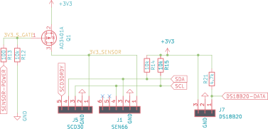
The sensor bank must include a high-side mosfet that will power cycle the 3.3V rail briefly (500-2000ms) if the one of sensors need to be reset (due to operation outside design conditions).
Construction
Passive components (resistors, capacitors) will be 2010 or 1812 package to be easy to solder by hand.
All board interfaces will be JST-PH connectors, including sensors, battery and solar panel connections.
Sensors wil be mounted off-board to facilitate positioning as specified in the reccomended engineering guides supplied by Sensirion.
Complete Schematic
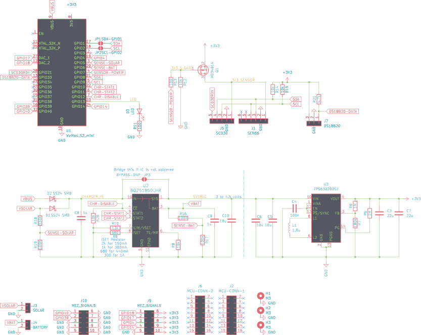
Power section Schematic
Sensor switching Schematic
MCU Schematic
Assembly instructions
Resistors
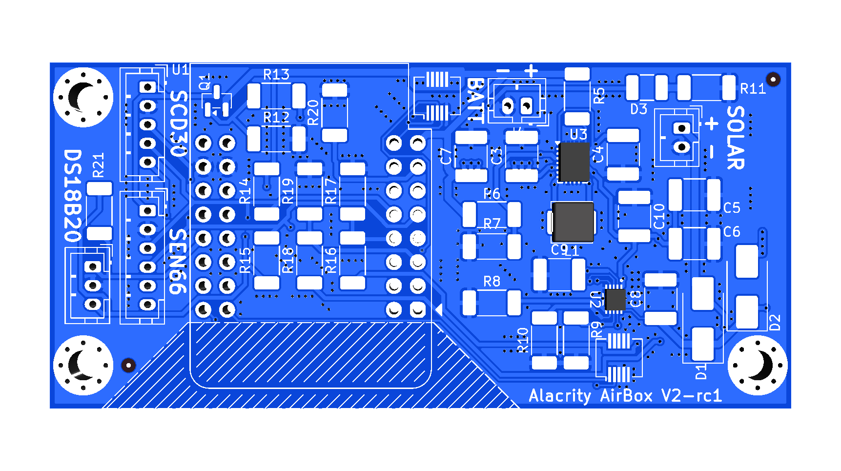
Start with the bare PCB. U2, U3 and L1 are alrady pre-soldered for you.
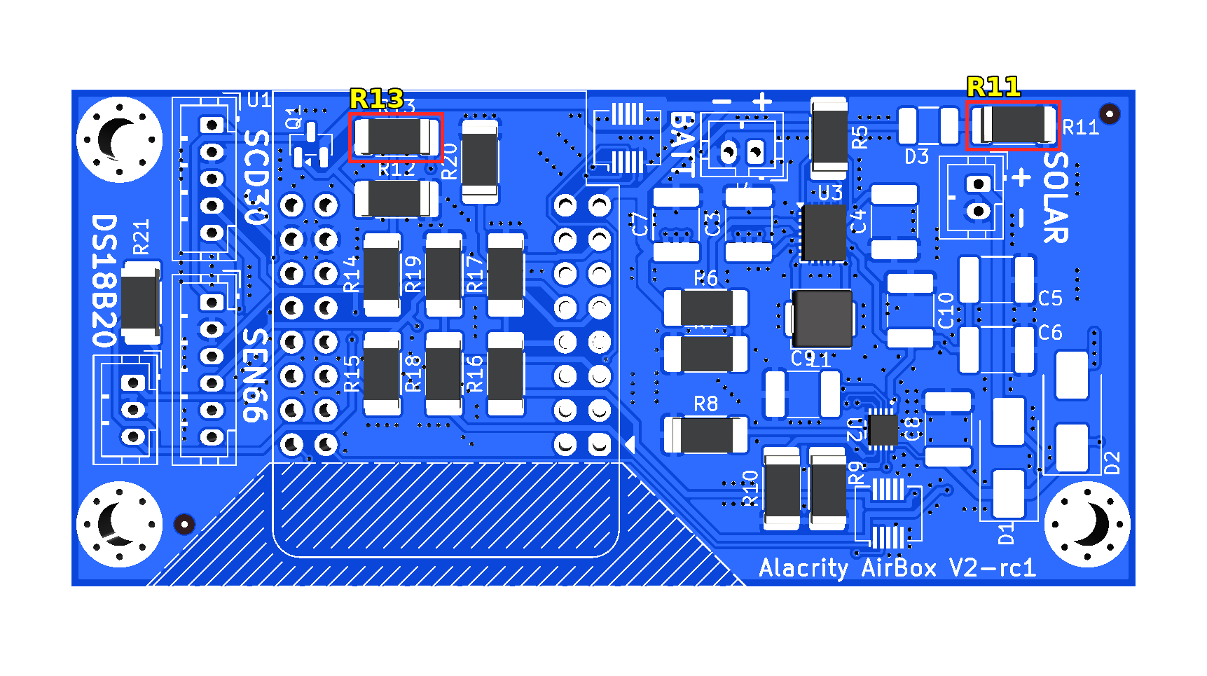
1 MΩ Resistor (total 2 resistors)
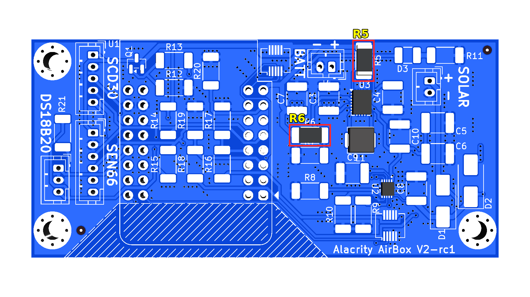
330 kΩ Resistor (total 1 resistor)
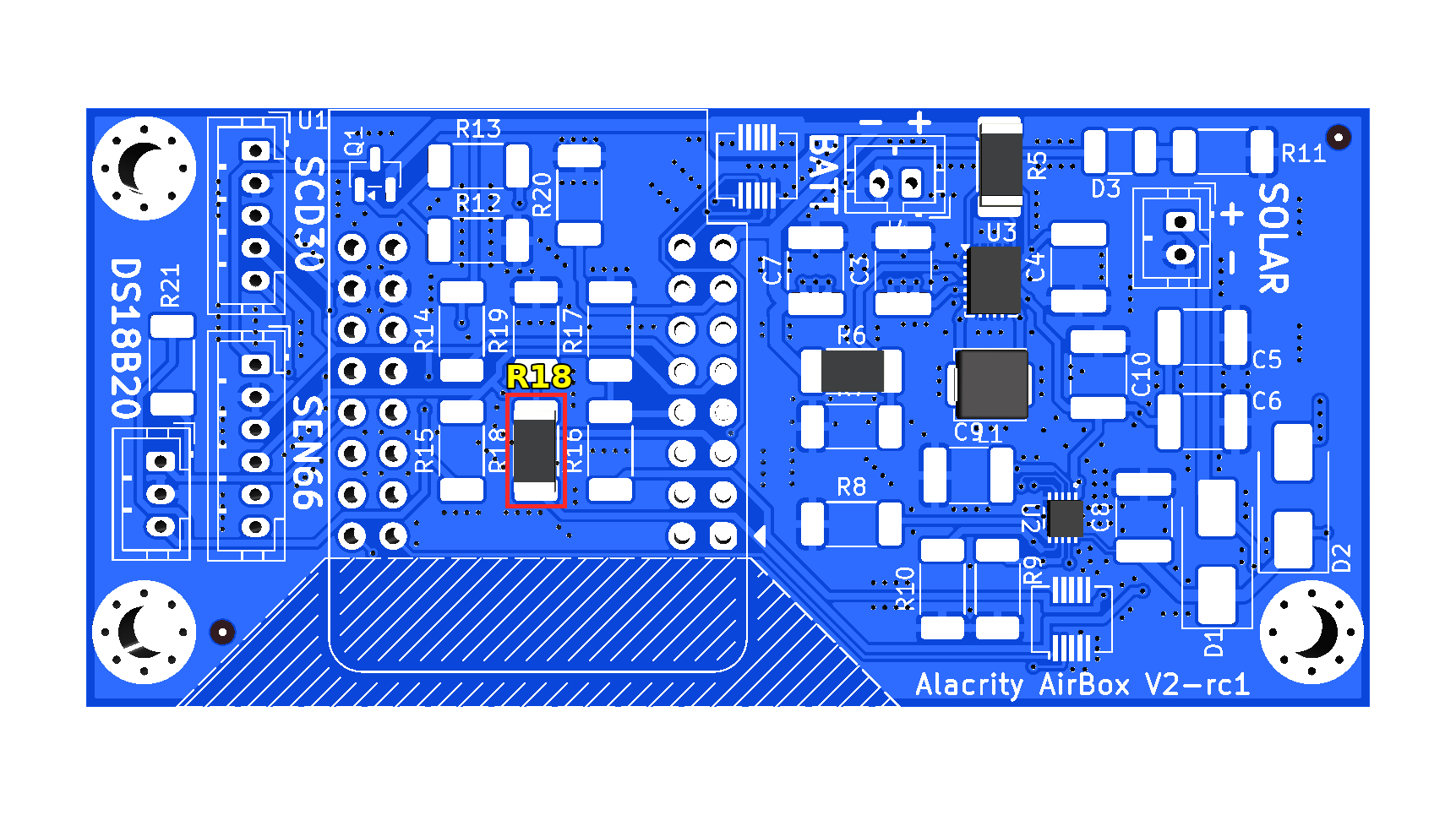
180 kΩ Resistor (total 1 resistor)
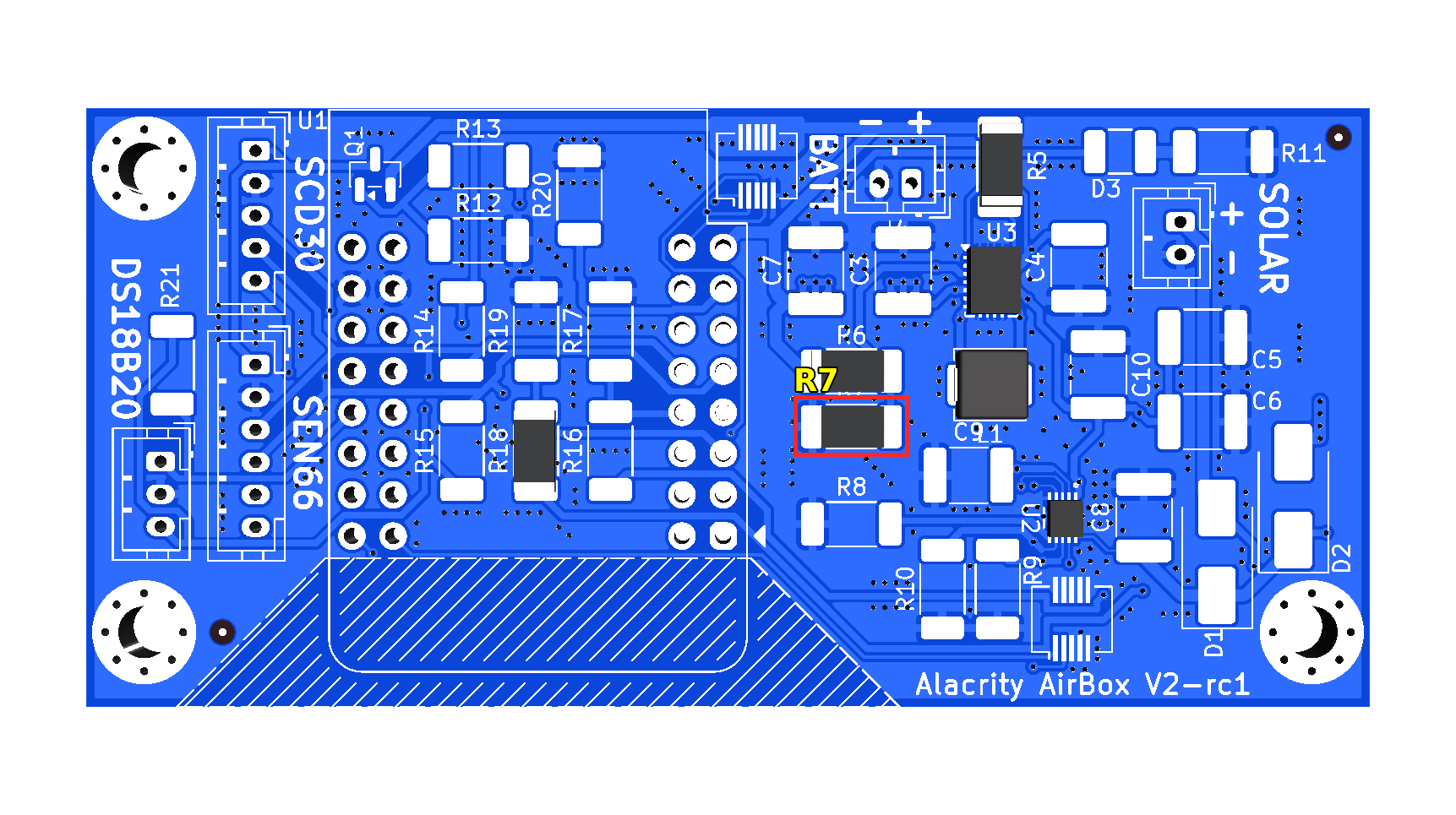
100 kΩ Resistor (total 3 resistors)
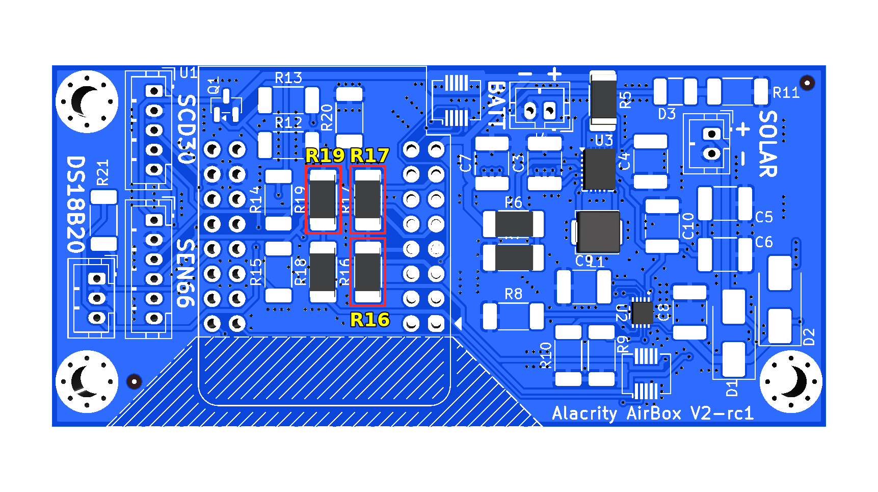
13 kΩ Resistor (total 1 resistor)
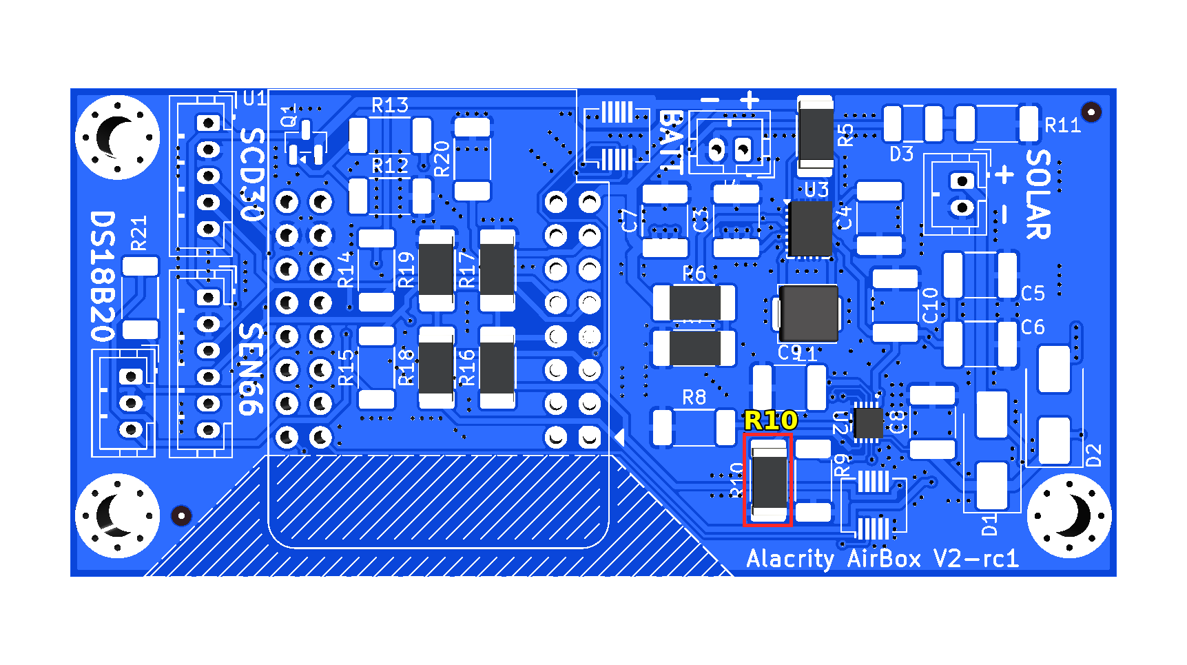
10 kΩ Resistor (total 5 resistors)
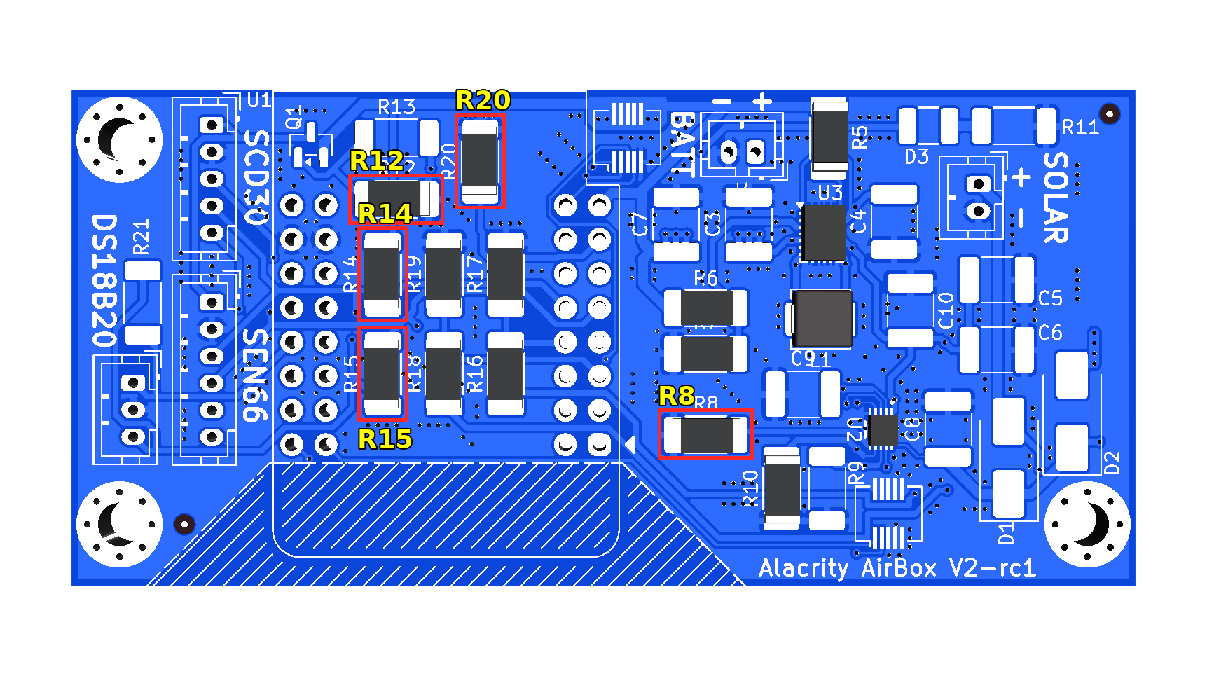
4.7 kΩ Resistor (total 1 resistor)
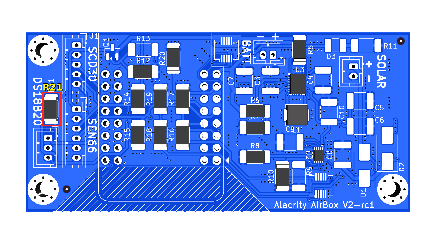
680 Ω Resistor (charge-set) (total 1 resistor)
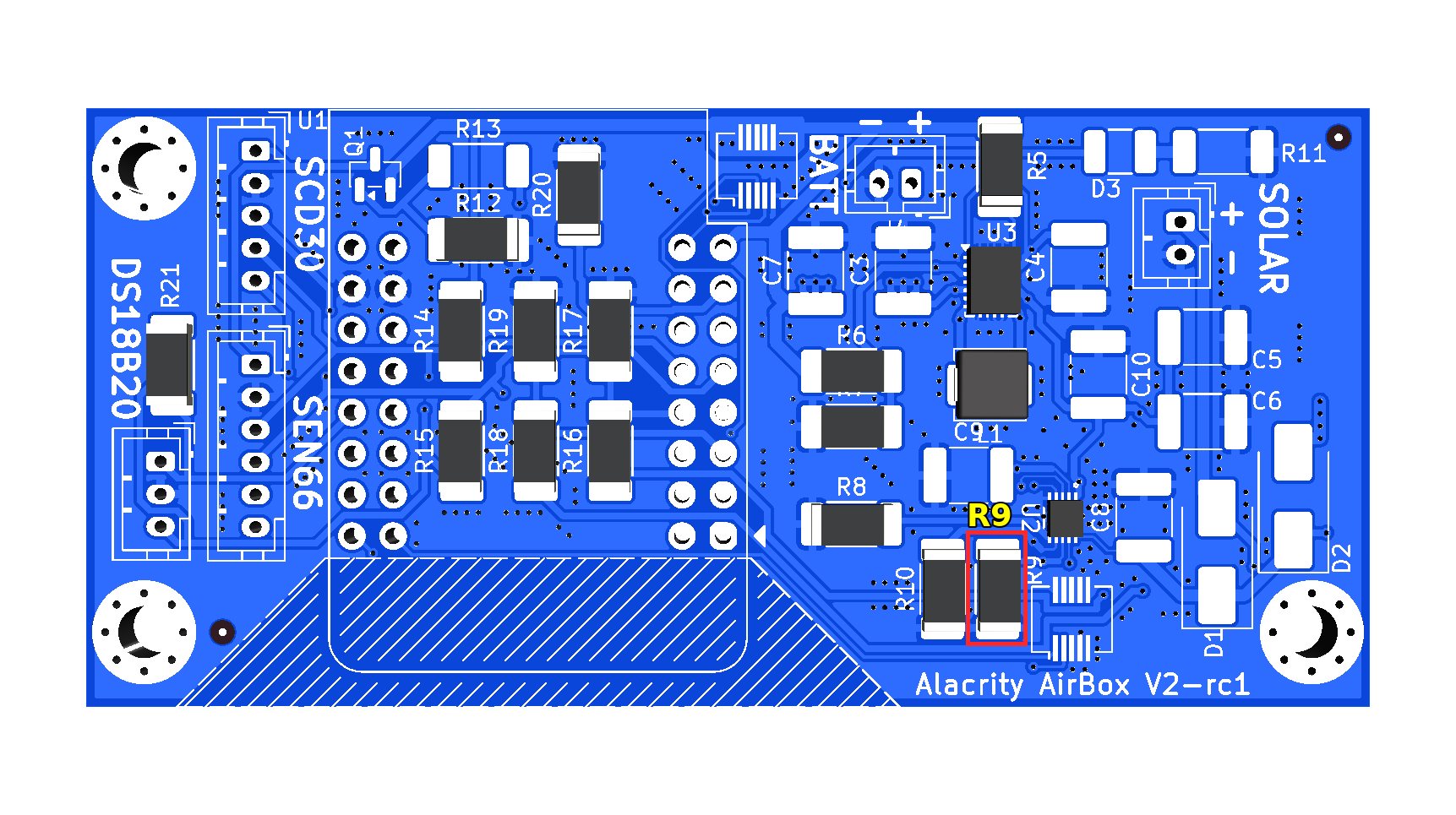
100 Ω Resistor (total 2 resistors)
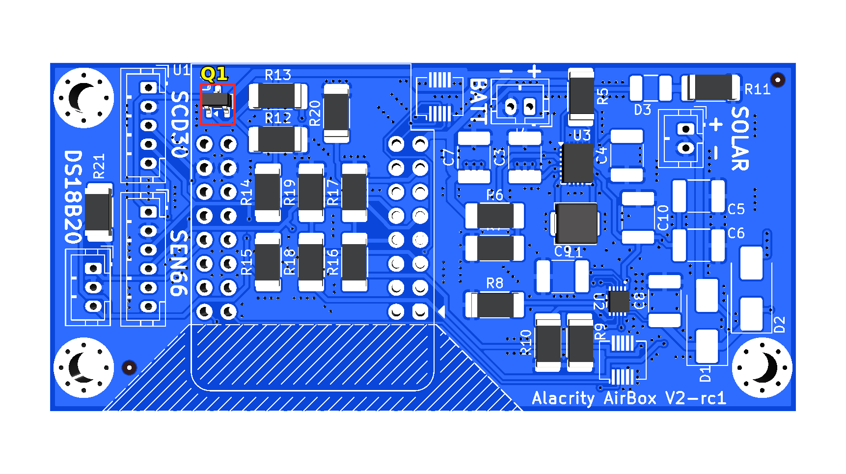
AO3401A P-MOSFET (total 1 MOSFET)
Status LED (total 1 LED)
LED's are polarized components - It's important to get the orientation right. The LED's circle is assymetric. Mount using the lens upwards, towards the board edge!
Ask Justin, Ilinca or another assistant for help placing this part.
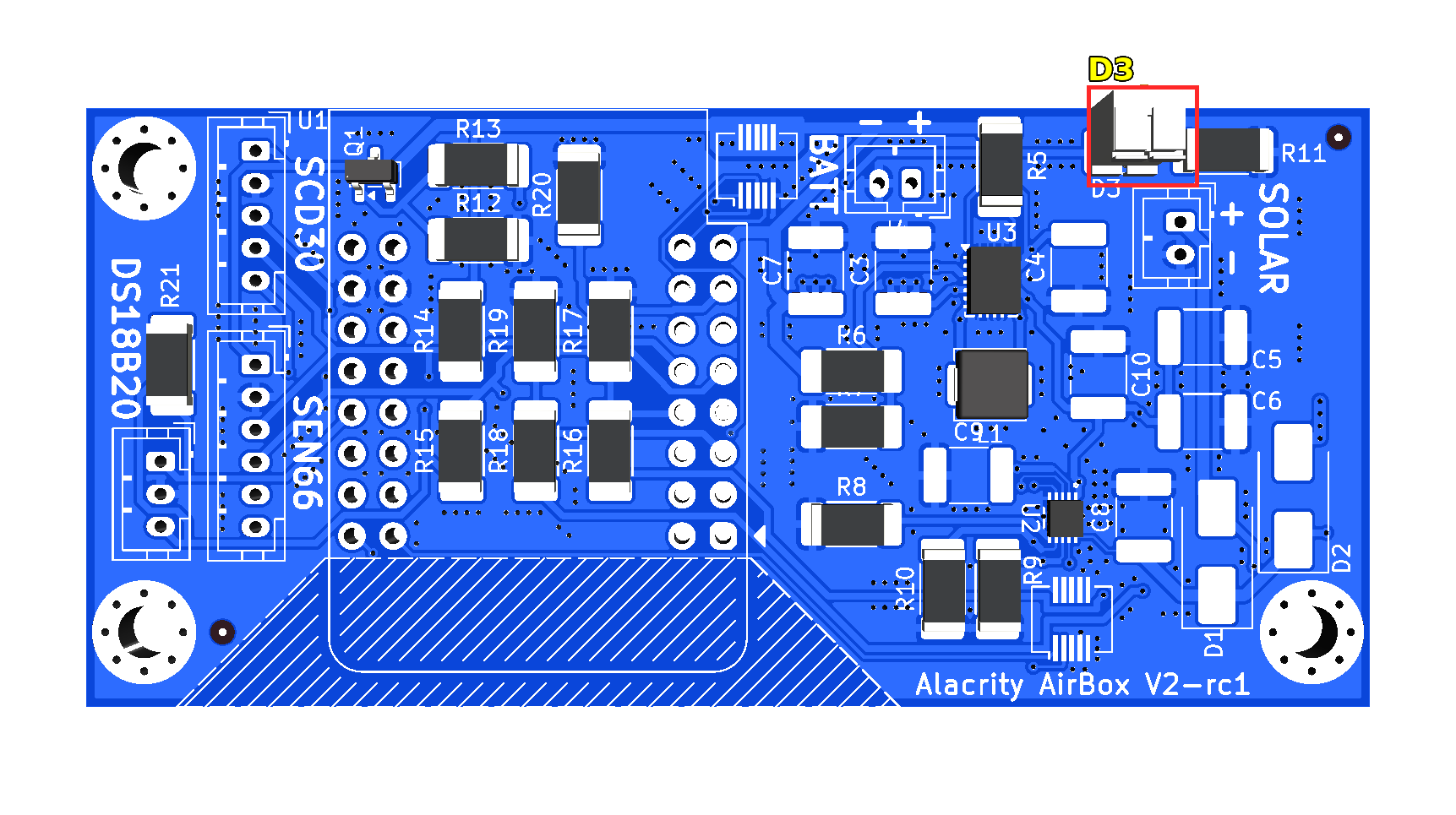
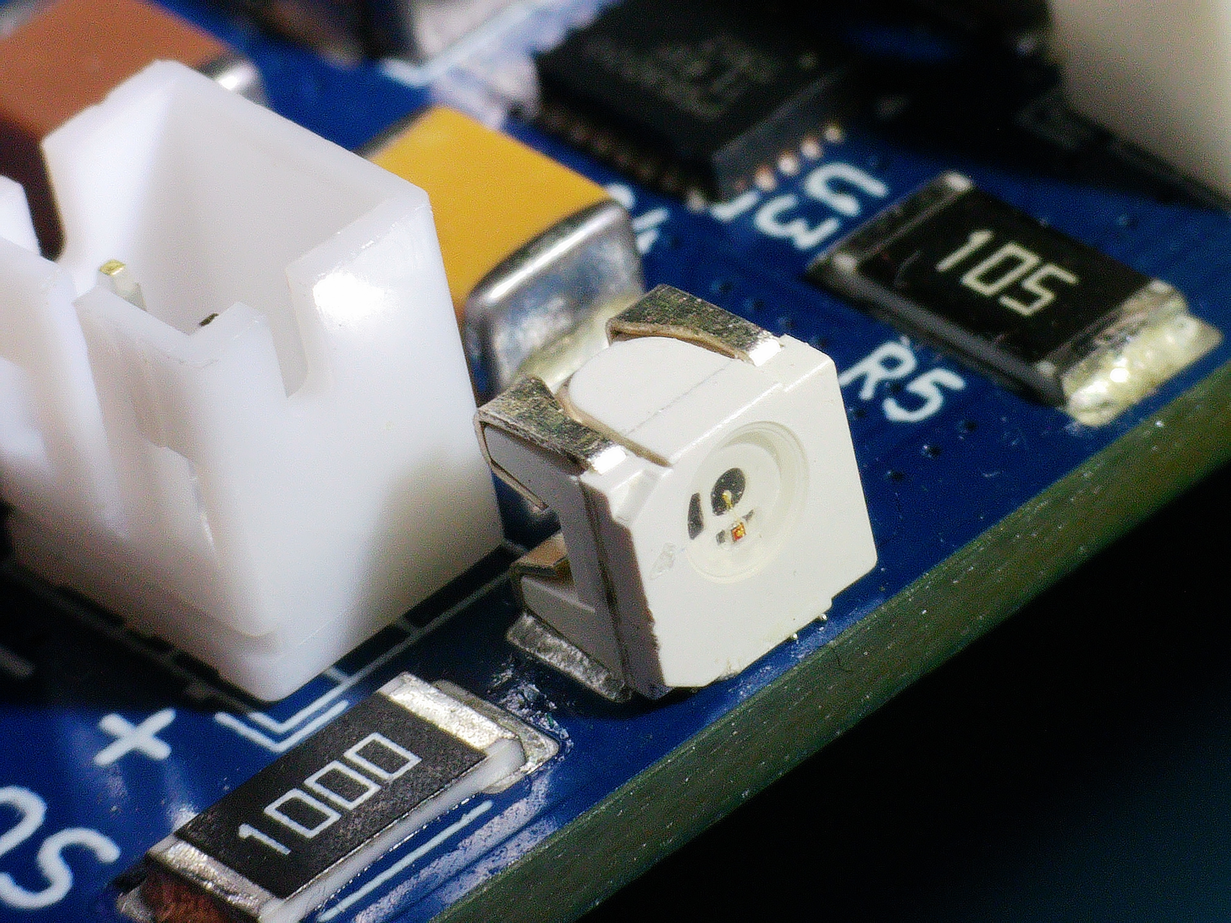
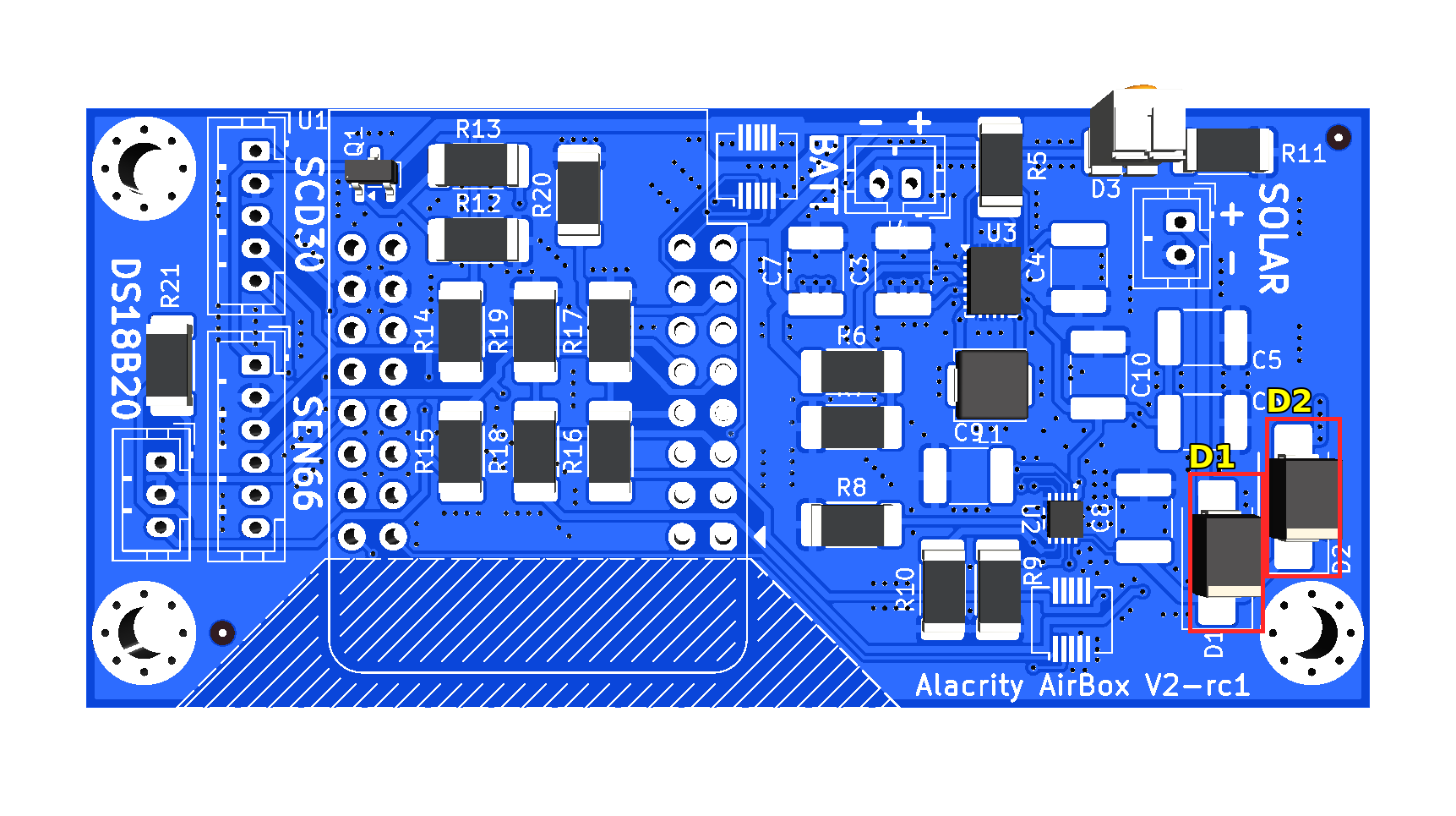
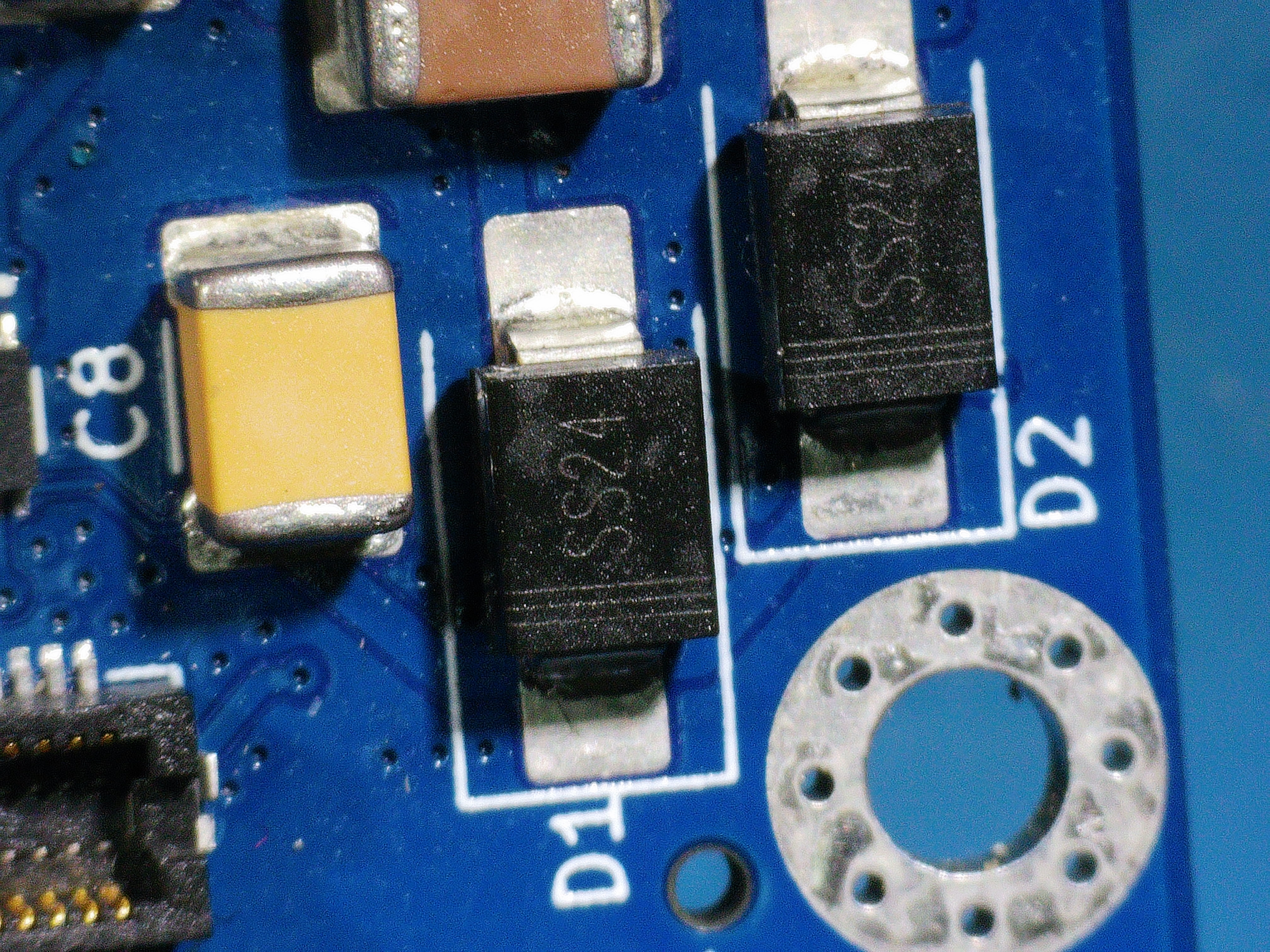
SS24 Schottky Diode (total 2 diodes)
Diodes are polarized components - It's important to get the orientation right. You will find three engraved lines on the anode of the diode.
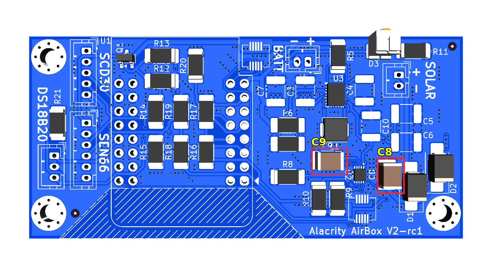
1 µF Capacitor (total 2 capacitors)
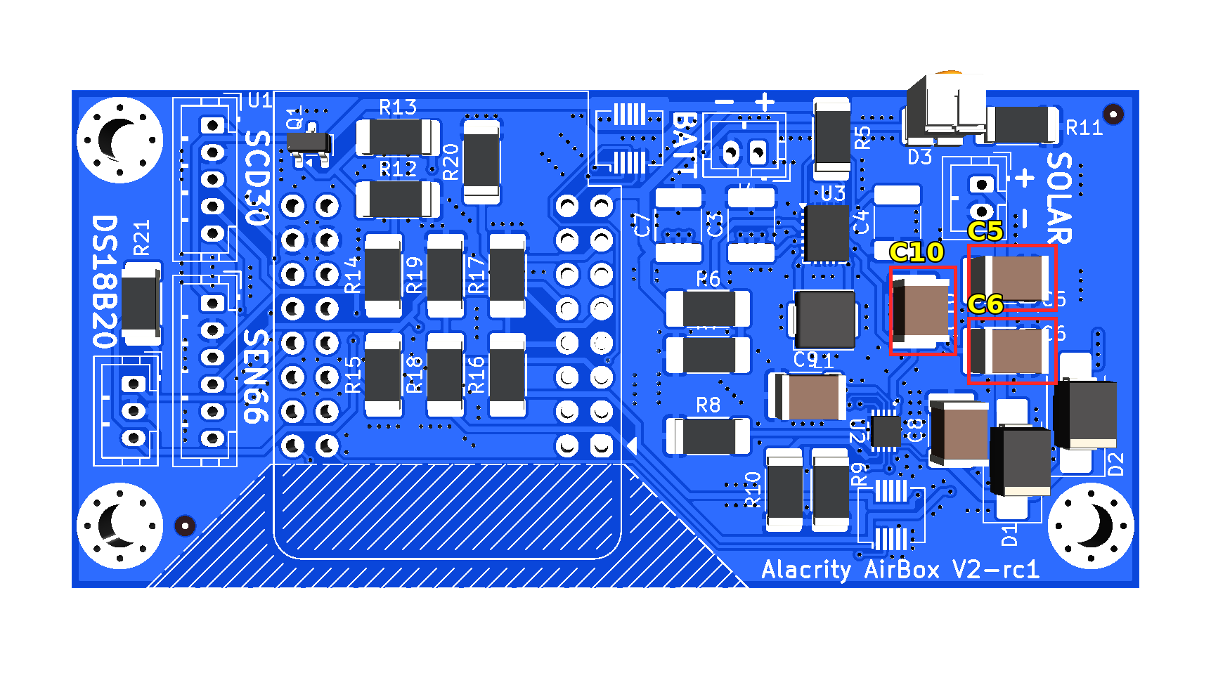
10 µF Capacitor (total 3 capacitors)
100 nF Capacitor (total 1 capacitor)
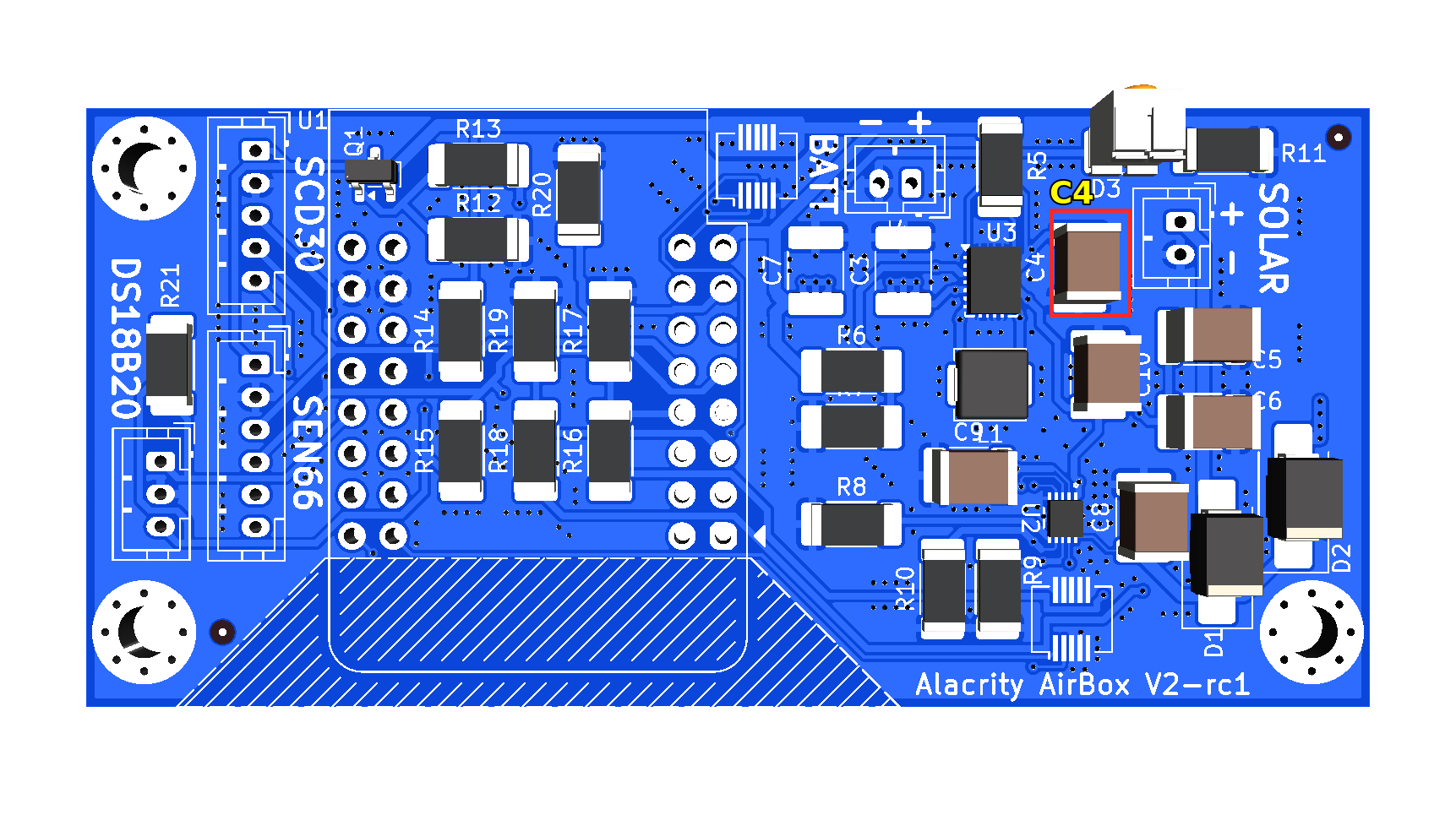
22 µF Capacitor (total 2 capacitors)
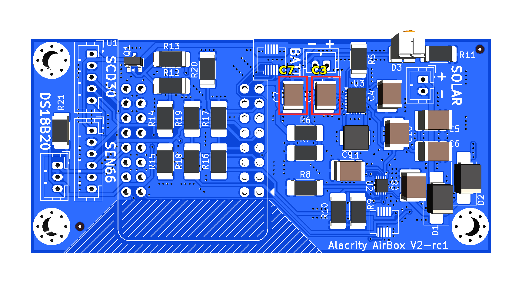
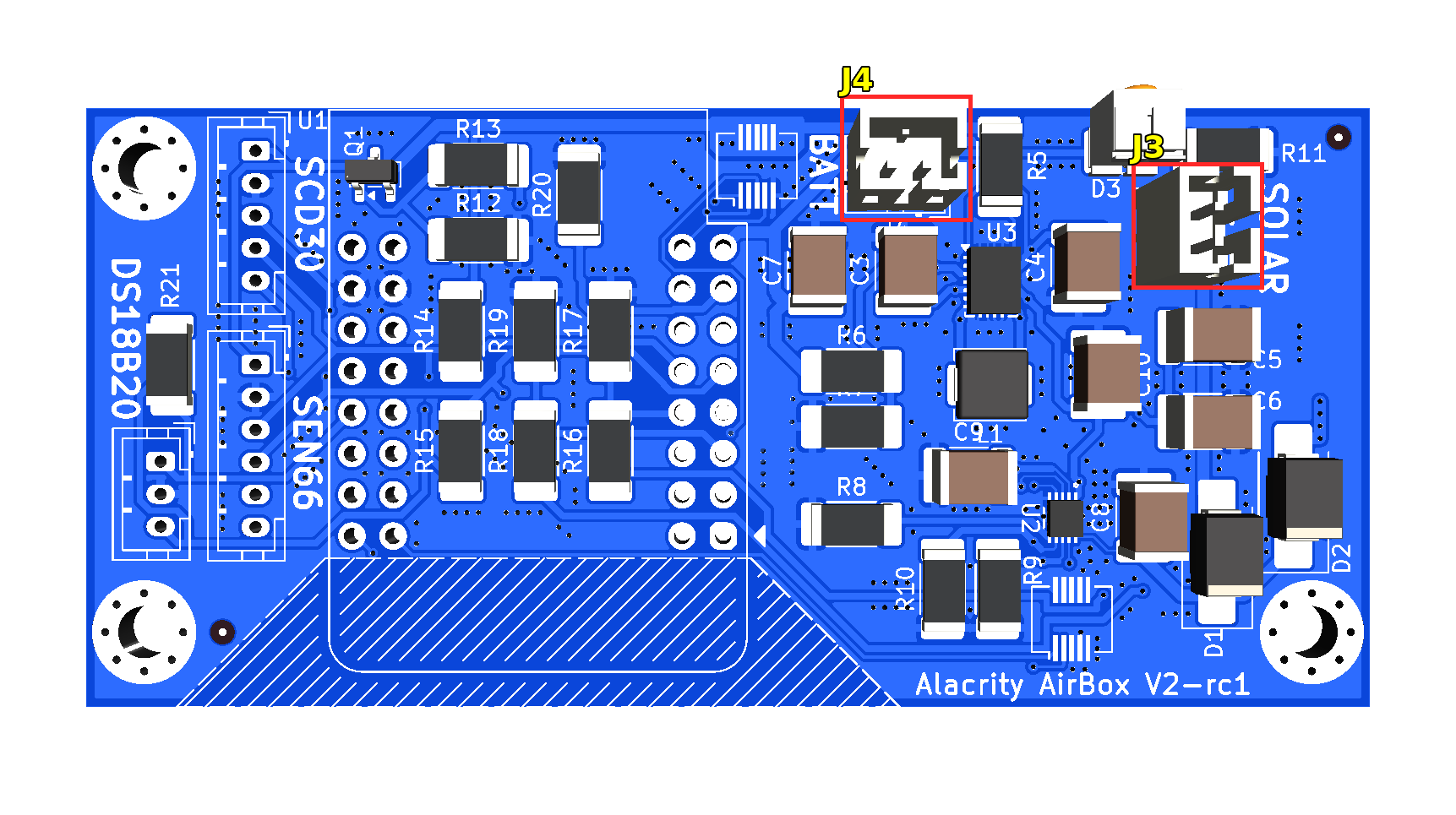
2-pin JST Connector (Solar + Battery) (total 2 connectors)
It is important to get the polarity of the power connectors right!
Battery connector tab towards the center of the board.
Solar connector tab towards the "SOLAR" writing.
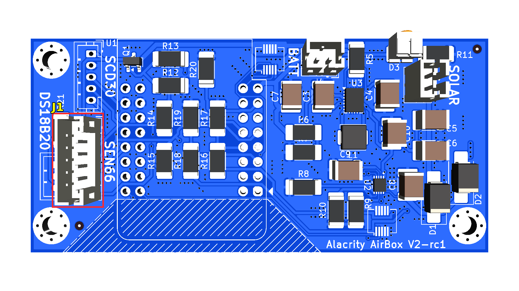
6-pin JST Connector (SEN66) (total 1 connector)
Place connector tab towards the center of the board or SEN66 text.
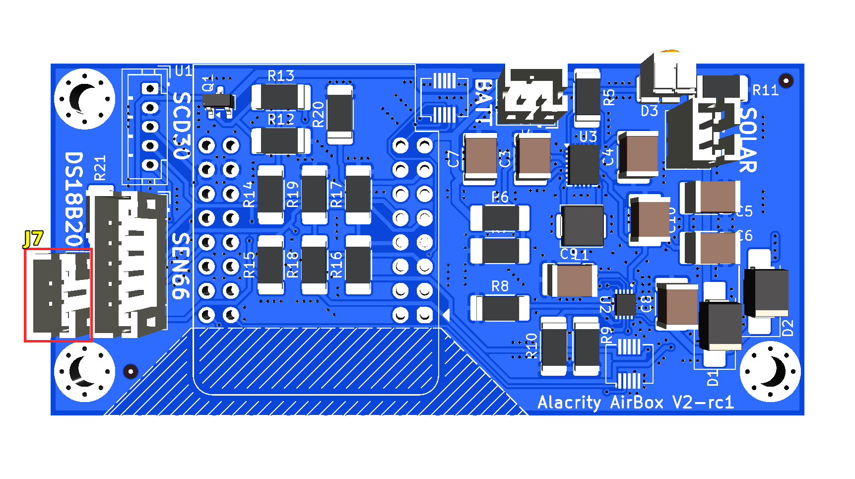
3-pin JST Connector (DS18B20) (total 1 connector)
Place connector tab towards the center of the board or SEN66 text.
Identical to the SEN66 connector.
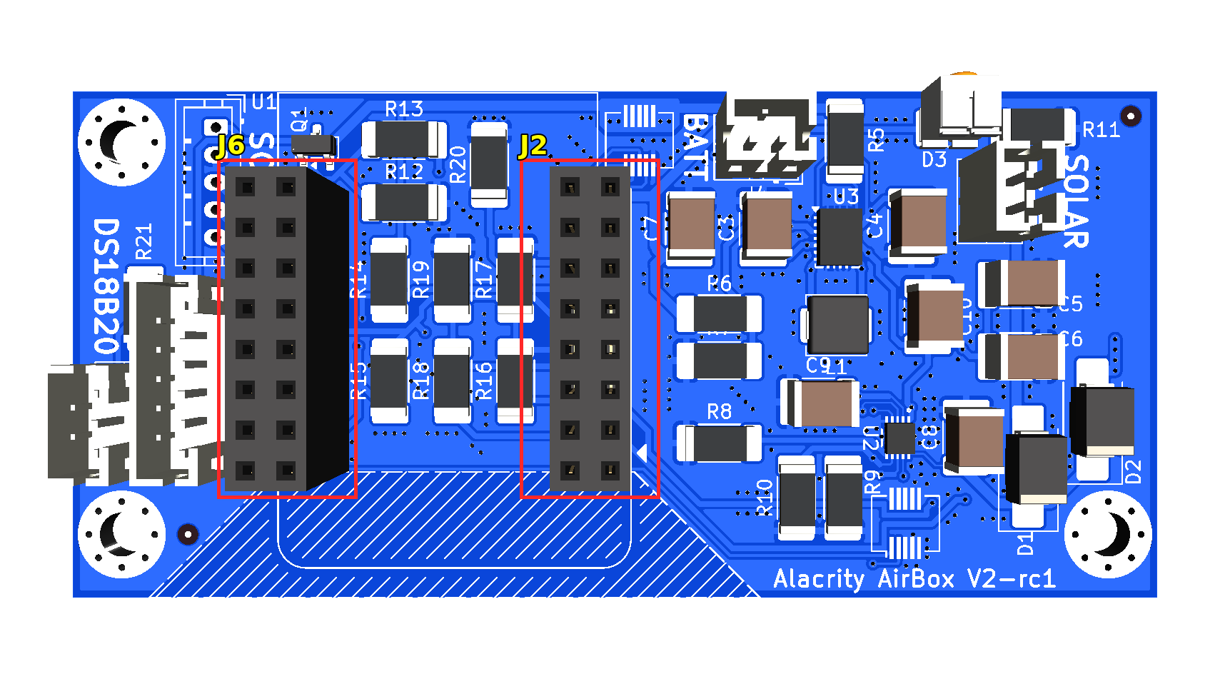
2×8 MCU Socket Header (total 2 headers)
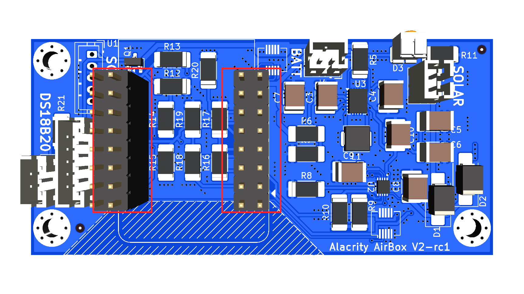
Insert MCU Header Pins (total 2 headers)
The pin headers have a long and short side. Insert the long side into the sockets, and the short side should stick up.
We will later solder the MCU to the short side.
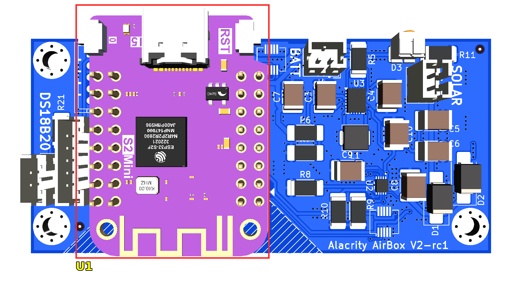
Solder WeMos S2 Mini Module (total 1 module)
Software
Firmware
Key considerations:
- SCD30 sensor sometimes reports 0.00ppm CO2 at startup. Do not publish this data to MQTT, but instead read in a loop every 15 seconds until concentration is not zero.
- When a SCD30 reset happens, all the data generated in a 15-minute window must be trashed.
Infrastructure & Data Flow
flowchart LR
    A["Airbox sensor<br/>builds JSON payload"]
    A -->|"HTTP POST"| B{"Authorization<br/>ApiKey"}
    B -->|"reject"| R["401 Unauthorized<br/>drop silently"]
    B -->|"pass"| J{"Validation<br>Schema & Values"}
    J -->|"fail"| K["400 Bad Request<br/>log and drop"]
    J -->|"pass"| C["Enrichment<br/>resolve device, installation<br/>add server timestamp"]
    C --> P["Persistence<br/>hypertable AIRBOX_READINGS"]
Firmware sends data to a HTTPS server under the following format using POST method:
Location: https://ingest.airbox.alacrity.ro/api/v2/submit
Authorization: Server must accept API token in any of the following headers:
Authorization: ApiKey XXXXXXXXXXApiKey: XXXXXXXXXXX-ApiKey: XXXXXXXXXX
Submitting a GET request to this page should show a HTML page with a small guide on how to submit data and a link to this documentation page here.
Only Content-Type header accepted must be application/json and the content of the request must conform with the schema:
{
  "geohash": "...",
  "charge": 0, # from 0 to 100 float
  "sun": false,
  "co2": 0
  "pm1": 0,
  "pm25": 0,
  "pm4": 0,
  "pm10": 0,
  "temp": 0,
  "hum": 0,
  "voc_index": 0,
  "nox_index": 0,
  "voc": 0,
  "nox": 0,
}
Failure to verify an ApiKey should not be logged.
String fields must be at most 100 characters long, and no other fields must be present. Any validation failure will drop the data point and log with a WARN severity the following information:
- Owner associated with the used ApiKey
- The kind of validation that failed
Numeric fields are optional. If they are not provided in the messagem they should be set to null.
The following fields must be enriched in the message with data fetched from the separate AIRBOX_INSTALLATIONS, by joining on the ApiKey received with the request:
"installation": "indoor" / "outdoor""device": "device id fetched from installations table""time": 3485898- unix timestamp when the data is received.
Then, the whole bunch of data goes to persist inside the AIRBOX_READINGS hypertable. The time, installation, device and geohash fields are mandatory and must be indexed. The rest of the fields represent concentrations and should be only set where measurements are available (persist null when absent).
When an airbox is not able to measure a specific measurement (like the SEN66-equipped airboxes for non-index VOC and NOX) those fields should be absent or set to undefined. Likewise, SCD30-equipped airboxes will publish only the co2 field (besides the three required fields).
AIRBOX_INSTALLATIONS Static Table
The table AIRBOX_INSTALLATIONS is static and will be manually updated by the administrators. The middleware should ensure the table exists, and if not, should create it.
CREATE TABLE IF NOT EXISTS AIRBOX_INSTALLATIONS (
    device_id       VARCHAR(100)  PRIMARY KEY,
    apikey          VARCHAR(100)  NOT NULL,
    owner_email     VARCHAR(100)  NOT NULL,
    co_owner1_email VARCHAR(100),
    co_owner2_email VARCHAR(100),
    installation    VARCHAR(100) NOT NULL,
    notes           TEXT,
    created_at      TIMESTAMP WITH TIME ZONE DEFAULT NOW()
);
In future iterations, we will implement a GUI for editing this table. Fow now, manual edits.
Data presentation
The main user interaction website is airbox.alacrity.ro. Here, we will have a main landing page with a short description of the project. A button or link will lead to the public grafana dashboard that serves the outdoor instances.
Grafana runs on /g/ base url on the aforementioned domain, and exposes a single dashboard for all outdoor stations and one dashboard per indoor station.
Grafana is configued with SSO, connected to our Authentik instance for administration.
indoordashboard automated provisioning will go unimplemented for now as we are not actively provisioning this variant.
Previous iterations
After initial testing with mock data, we have discovered that Prometheus is not suitable for long-term data retention. We will evaluate wether Mimir or TimescaleDB would fit the purpose better.
Telegraf also cannot be trusted with unsanitized data, therefore we are opting to build a middleware that transfers data from MQTT to PGSQL, while also ensuring data sanitization.
Connecting an AirBox to WiFi
The WiFi name, password and the station location (geohash) are not written in the code. They live in the board's flash memory and are entered through setup mode: the AirBox opens its own WiFi hotspot with a small configuration page. You can change them any time without reflashing.
What you need
- the AirBox, powered (USB cable or a charged battery, either works)
- a phone or laptop with WiFi
- the name and password of the network the station should use
- the geohash of the spot where the station will live
The ESP32 only speaks 2.4 GHz WiFi. A network that is 5 GHz only will never be found, no matter how correct the password is. Networks that need a login page (hotel or school portals) do not work either, the station has no browser to log in with.
Step 1: enter setup mode
Press the setup button and keep it held for 15 seconds. This works from any state, even while the station is sleeping: the button wakes it up.
You know you are in setup mode when the LED stays solid on.
A freshly flashed board has no WiFi settings at all, so it boots straight into setup mode by itself. In that case skip the button and go to step 2.
If you release the button too early the station just continues whatever it was doing. Try again and count the full 15 seconds.
Step 2: connect to the AirBox hotspot
On your phone or laptop, join this network:
- Network name:
AirBox-Setup - Password:
airbox-setup
Your phone will likely warn that this network has no internet. That is normal, stay connected anyway.
Step 3: open the configuration page
On most phones the page pops up on its own a few seconds after connecting (the same way hotel login pages do). If nothing appears, open a browser and go to:
http://192.168.4.1
Step 4: fill in the form
The page has three fields:
- WiFi SSID: the exact name of the network. Spelling and capital letters matter.
- WiFi password: the network password. Leave empty for an open network.
- Geohash: the station's location, encoded as a short string of letters and digits. Look yours up with an online geohash tool (search "geohash map", e.g. geohash.softeng.co), zoom to the station's spot and copy a 7 or 8 character hash.
Press Save & reboot. The station stores the values and restarts in normal mode.
If you only wanted to look and change nothing, press Leave setup mode instead: the station reboots and keeps its old settings.
Step 5: check that it worked
Be patient here. The station does not connect immediately after the reboot: it first checks the temperature probe, then preheats the air sensor for 5 minutes, and only then connects and uploads. So the first data appears on the dashboard about 6 to 7 minutes after the reboot, and then roughly every 16 minutes.
If you have a USB cable and the serial monitor open (115200 baud), you can watch it happen live: a connected line with an IP address, then a POST line and HTTP 200 (accepted).
When it does not work
- The hotspot never appears. The button was probably released early, hold it a full 15 seconds and watch for the solid LED. Also check the board has power at all.
- The page does not open. Type
http://192.168.4.1in the browser by hand, and make sure your phone did not silently jump back to its usual WiFi (some phones leave networks that have no internet). - No data after 20 minutes. Almost always the credentials: a typo in the name or password, or a 5 GHz only network. Hold the button 15 seconds and re-enter setup mode, the form shows the currently saved values so a typo is easy to spot. Weak signal at the mounting spot is the next suspect, test the station closer to the router first.
- It uploads at home but not at the deployment site. Same checks, different network: the site's WiFi name and password must be saved on the station while you are there, or before you go, using a phone hotspot with the same name and password as the site network is a handy trick.
Setup mode can be entered as many times as you like, nothing breaks by trying.
Development timeline
PCB Development timeline:
| 12 April | 17 April | 18 April | 20 April | 23 April | 3 May | 6 May |
|---|---|---|---|---|---|---|
| PCB Development started | PCB development finished | RCB Review finished & Ordered at JLCPCB + LCSC | PCB Fab finished & QFN automated assembly started | PCB Shipped | PCB Arrived in Bucharest | Assembly of the first prototype finished |
Course material development timeline:
| 18 April | 30 April | 3 May | 8 May |
|---|---|---|---|
| Course material development started after PCB design is finished | Course deadline, follows review process for refinement | Review finished and changes implemented | Course is ready for demo |
BOM
This bom is aimed at protptyping with pre-assembled PCB for a few pieces. Once testing is positive, we will provide a BOM for manual assembly:
- PCB (Assembled with all components at JLCPCB) - Download design files from Github
- 3x SEN66 Sensor - SOSElectronic
- 3x SCD30 Sensor - Already have enough for prototyping
- 3 SEN66 cable - SOSElectronic
- JST-PH connectors - already have enough
- JST-XH connectors - already have enough
Datasheets
| SEN66 | SEN55 | SCD30 | BQ25185 |
|---|
Previous prototypes
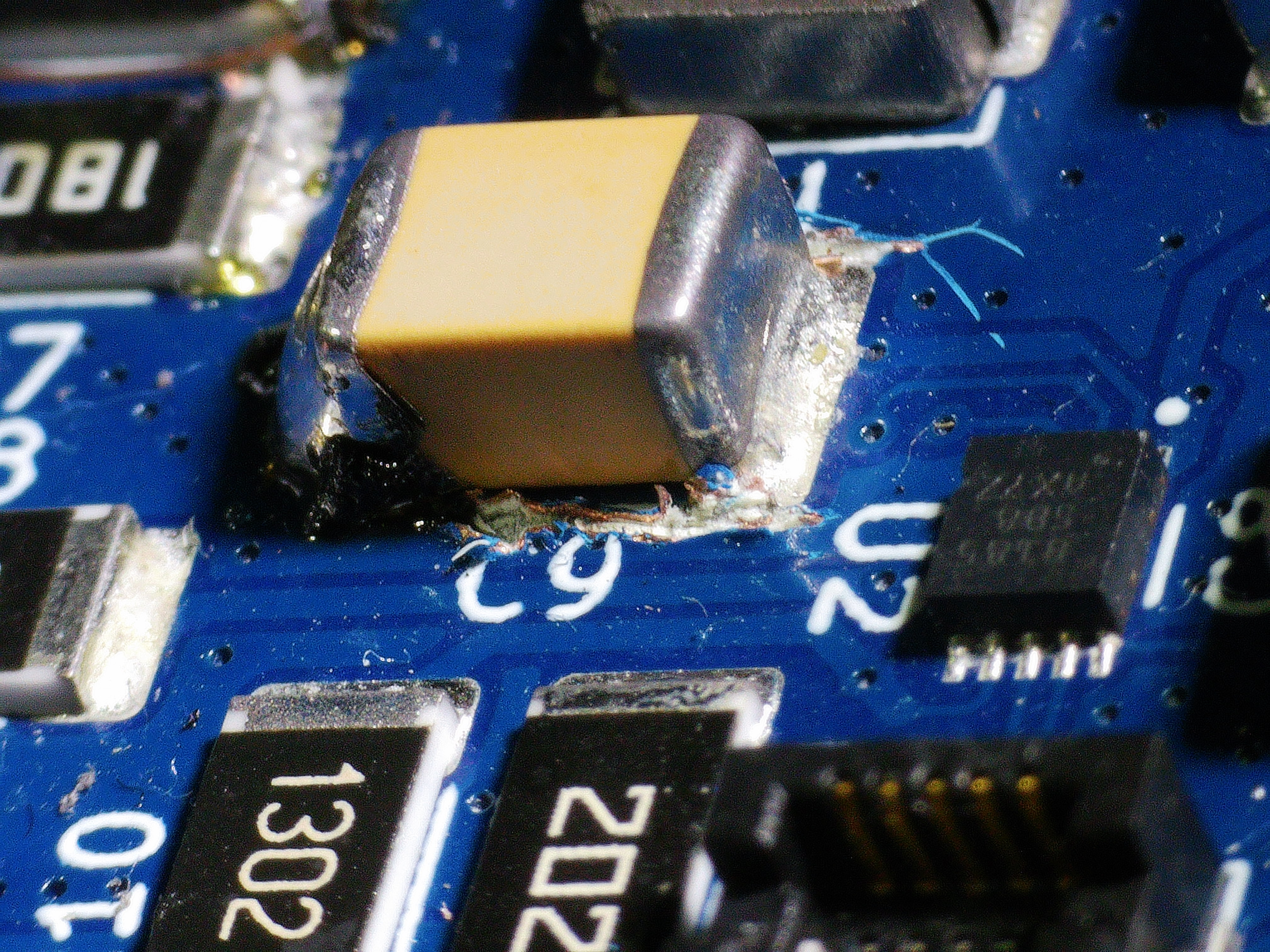
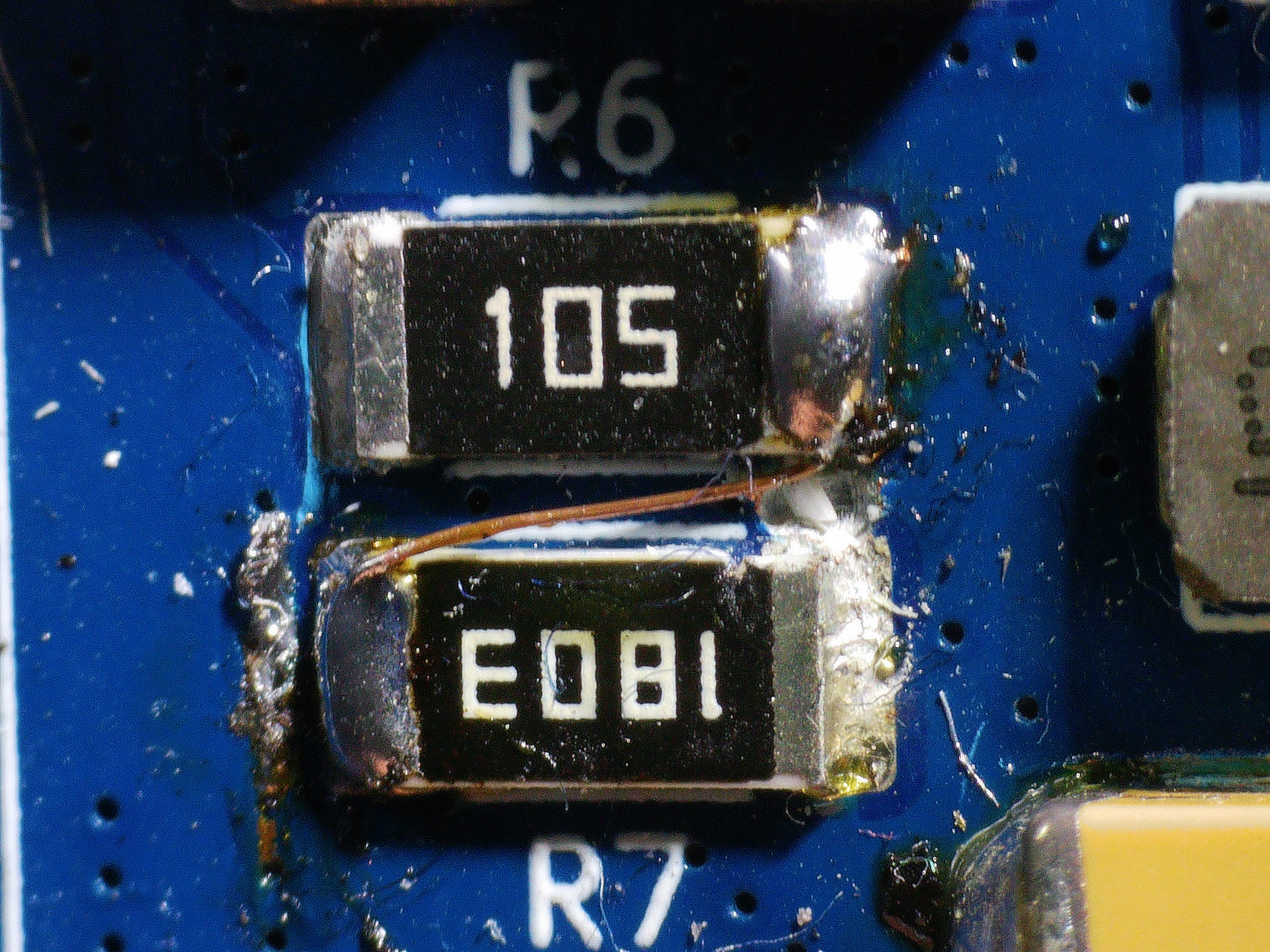
In a previous prototype, the nets of R7 and C9 got flipped 180 degrees by mistake, during a schematic-only reorganization. This caused ground planes to form around the wrong pin, shorting to ground the Vin line.
The fix was to:
- Cut the GND connections of the right pad of C9, left and right of the capacitor
- Scratch the GND copper near the left pad of C9 and bridge the capacitor to the exposed GND.
- Cut the short trace between R6 and R7.
- Wire a jumper from the left pad of R7 to the right pad of R6.
 |
 |
|---|